Given the complex biomechanics governing full-arch restorations, understanding the structural layout of the anterior-posterior (AP) spread is fundamental to preventing long-term mechanical and biological failures. This training guide focuses on the engineering principles behind full-arch implant rehabilitations.
AP Spread Fundamentals & Measurement Metrics
Defining the Geometric Parameters
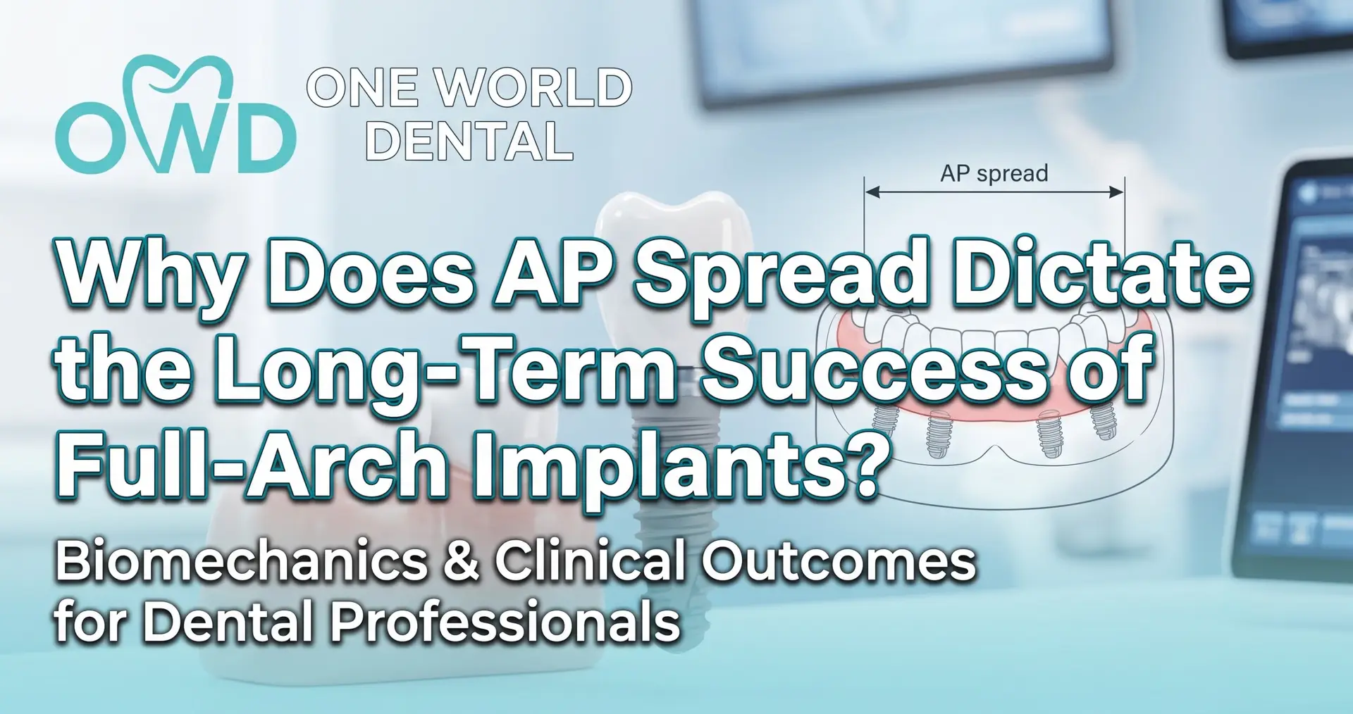
Anterior-Posterior (AP) spread is defined as the linear distance between two parallel lines: one passing through the distal-most margins of the terminal implants, and the other passing through the anterior-most margin of the leading implant.
In clinical mechanics, this distance forms the stabilizing base of the fixed prosthetic framework. The broader this base, the more effectively the entire system redistributes non-axial, rotational, and shear forces across the supporting implant fixtures and surrounding alveolar bone.
The Mechanical Relationship: Cantilever Length to AP Spread
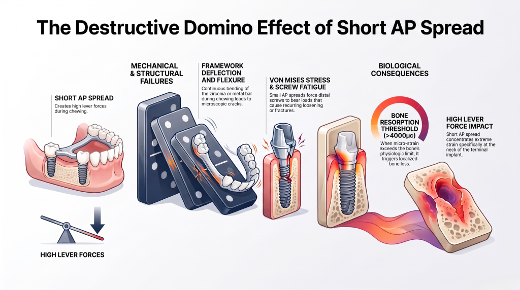
The relationship between AP spread and the allowable distal cantilever length is governed by the principles of a Class I lever system. In this model, the terminal implant acts as the fulcrum. When a patient exerts an occlusal load on the distal cantilever extension, it creates a rotational bending moment. This moment multiplies stress across the entire system.
To maintain structural equilibrium, clinicians must adhere to strict mathematical rules:
The Mandibular Limit: The distal cantilever should not exceed 1.5 times the measured AP spread ($\text{Cantilever} \le 1.5 \times \text{AP Spread}$).
The Maxillary Limit: Due to lower bone mineral density and thin cortical plates, the cantilever must be restricted to 1.0 times the AP spread ($\text{Cantilever} \le 1.0 \times \text{AP Spread}$).
Exceeding these mechanical boundaries generates high lever arms. This causes intense compressive loads at the terminal implant site and severe tensile forces pulling upward on the anterior implants.
Precise Intraoral Verification Protocols
Accurate measurement begins during three-dimensional virtual planning and must be verified before final framework fabrication. Clinicians should use the following protocols to evaluate this metric:
Pre-surgical CBCT Diagnostics: Utilize cross-sectional cone-beam computed tomography to measure the distance between planned implant centers along the curvature of the restorative arch form.
Prosthetic Verification Jigs: Splint open-tray impression copings intraorally using low-shrinkage pattern resin or bis-acrylic materials. This creates a rigid index to prevent displacement during master cast fabrication.
Laboratory Cast Assessment: On the master cast, draw a reference line across the center of the two most anterior implants. Draw a parallel line across the distal margins of the most posterior implants. The distance between these parallel lines is the true AP spread.
Full-Arch Biomechanics: Stress & Load Distribution
Finite Element Analysis (FEA) Modeling
Three-dimensional finite element analysis (FEA) shows exactly how stress behaves within the surrounding bone and prosthetic components. When the AP spread is insufficient, occlusal forces concentrate heavily at the terminal implant site.
FEA models demonstrate that maximizing the AP spread spreads the load more evenly. This prevents localized micro-strain areas that can cause early bone loss.
All-on-4 vs. All-on-5 Loading Dynamics
Adding a fifth or sixth implant changes the structural behavior of the system, but it does not fix a poor AP spread. If five implants are placed in a narrow, straight line across the anterior premaxilla, the AP spread remains short. The distal cantilevers will still experience high destructive forces.
An All-on-4 configuration with a wide AP spread—achieved by tilting the posterior implants—is biomechanically superior to an All-on-5 configuration with a narrow AP spread.
Displacement Forces under Occlusal Loading
When a patient chews, a short AP spread allows the prosthetic framework to flex and shift under load. This micromovement can disturb the bone-to-implant interface during early healing. Maximizing the AP spread increases the rigidity of the system. This controls displacement forces and keeps full-arch restorations stable over the long term.
Structural Integrity & Component Longevity
Von Mises Stress Analysis
Von Mises stress values help predict where a material is likely to fail under complex loads. When the AP spread is too small, the distal abutment screws bear the brunt of this force. Over time, these high stress levels lead to metal fatigue. This causes recurring screw loosening or catastrophic fractures of the prosthetic or retaining screws.
Strains at the Site of Cortical and Cancellous Bone
The jawbone responds dynamically to mechanical strain. Healthy stimulation keeps bone intact, but excessive strain causes damage.
[Short AP Spread] ➔ [High Lever Forces] ➔ [Micro-strain Exceeds 4000µε] ➔ [Bone Resorption]
When a short AP spread creates high lever forces, the bone surrounding the neck of the terminal implant experiences extreme strain. If this strain exceeds the bone’s physiologic threshold (typically above $4000 \mu\epsilon$), it triggers localized bone resorption.
Superstructure Deflection and Flexure
Every material bends slightly under pressure. A long cantilever resting on a short AP spread causes the framework to flex continuously during chewing. This ongoing flexure creates internal stress within the metal bar or zirconia framework. Eventually, this leads to microscopic cracks and structural failure of the prosthesis.
Clinical Consequences of Compromised AP Spread
Mechanical Failures
When clinicians fail to optimize the AP spread, they often face recurring mechanical issues. The most common early sign is the repeated loosening of prosthetic retention screws. If ignored, this extra stress can lead to fractured abutment screws. In severe cases, it can even snap cast gold, titanium, or cobalt-chromium framework bars under normal chewing forces.
Biological Failures and Crestal Bone Loss
High mechanical stress and biological inflammation often reinforce each other. Excessive strain at the crestal bone level can cause micro-fractures in the bone. This creates a pathway for bacterial invasion. The resulting bone loss destroys the protective seal of the soft tissue, increasing the risk of peri-implantitis and rapid bone damage around terminal implants.
The “Teeter-Totter” Effect Explained
A short AP spread turns the distal implant into a literal pivot point for a teeter-totter. Biting down on the back teeth pushes the cantilever down, which forces the front of the prosthesis up. This constant rocking motion subjects the anterior implants to severe upward pulling forces, threatening their integration over time.
Strategic Solutions for Compromised Anatomy
Utilizing Tilted Posterior Implants
When posterior bone volume is limited by the maxillary sinus or mental nerve, tilting the posterior implants 30 to 45 degrees is a highly effective solution. This exit angle shifts the restorative platform further to the distal. This naturally widens the AP spread and safely shortens or eliminates the distal cantilever.
Implant Placement Strategy
Average AP Spread
Allowable Cantilever
Atrophic Anatomy Suitability
Straight/Axial Only
Narrow ($10-12\text{ mm}$)
Minimal ($\text{Max } 10\text{ mm}$)
Poor (Requires extensive bone grafting)
Tilted Posterior (All-on-4)
Wide ($15-22\text{ mm}$)
Moderate (Up to $15\text{ mm}$)
Excellent (Bypasses maxillary sinus/mental nerve)
Zygomatic/Pterygoid
Maximum ($25+\text{ mm}$)
Zero to Minimal
Superior (For severe maxilla atrophy)
Alternative Anchorage Options
For severe bone loss in the upper jaw, standard tilted implants may not be an option. In these cases, anchoring into the zygomatic bone or pterygoid maxillary complex provides excellent support. These advanced techniques offer solid structural points far to the back, expanding the AP spread without bone grafts.
Shortened Dental Arch (SDA) Protocol
If a patient’s anatomy limits the AP spread and prevents tilting the implants, the best approach is to shorten the dental arch. Stopping the restoration at the first molar or second premolar reduces the cantilever length. This limits chewing forces to the stable area directly supported by the implants.
Material Selection Criteria
Monolithic Zirconia vs. Metal-Acrylic
Prosthetic materials handle stress in very different ways:
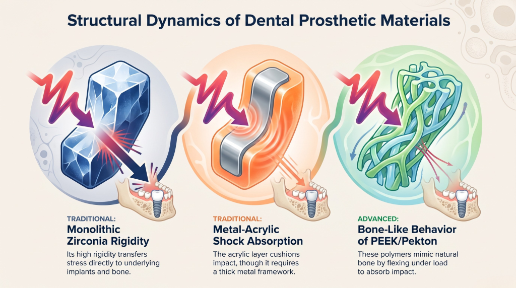
Monolithic Zirconia: Offers excellent strength and resists wear, but it is highly rigid. If the AP spread is short, this rigidity transfers all the chewing stress directly to the underlying implants and bone.
Metal-Acrylic Hybrids: The acrylic layer acts as a shock absorber, cushioning impact forces. However, the underlying metal framework must be thick enough to prevent bending and material breakage.
High-Performance Polymers (PEEK/Pekton)
High-performance polymers like PEEK and Pekton behave a lot like natural human bone. They absorb impact well and flex slightly under load, protecting the implants from sudden heavy forces. These materials are highly effective options when an ideal AP spread cannot be achieved.
Clinical Summary and Continuing Education
Long-term success in full-arch rehabilitation depends on balancing engineering with biology. Clinicians should follow the 1:1.5 cantilever rule for the lower jaw and keep a 1:1 ratio for the upper jaw. Managing this ratio prevents mechanical overloads and protects both the components and the bone.
Full-Arch Treatment Planning Checklist
Evaluate bone volume using CBCT to find the best possible positions for the front and back implants.
Use tilted posterior, zygomatic, or pterygoid implants to maximize the AP spread whenever possible.
Verify the accuracy of the master model using a rigid intraoral verification jig.
Calculate the allowable cantilever length based on the final measured AP spread.
Choose prosthetic materials that match the patient’s bite forces and the layout of the implants.
For clinicians looking to master these workflows and protect their full-arch cases against mechanical failure, advanced education is essential. One World Dental provides comprehensive, evidence-based continuing education programs.
These courses give oral healthcare professionals the practical skills and advanced engineering insights needed to deliver predictable, long-lasting implant solutions.
Advanced Implantology FAQs (People Also Ask)
What is the clinical definition of anterior-posterior (AP) spread?
AP spread is the linear distance measured from the front edge of the most anterior implant to the back edge of the most posterior implant. This dimension determines the structural stability of a full-arch restoration.
Why is the cantilever limitation different between the maxilla and mandible?
The upper jaw consists of less dense, softer bone (Type III and IV), which is more vulnerable to damage from heavy forces. The lower jaw features dense cortical bone (Type I and II) that can safely handle higher lever forces.
Does adding more implants compensate for a poor AP spread?
No. Placing extra implants in a straight line across the front of the jaw does not widen the AP spread. The system will still face high lever forces on any unsupported extensions.
How do tilted implants improve the AP spread?
Tilting posterior implants at 30 to 45 degrees allows the tops of the implants to emerge further back in the mouth. This broadens the overall support base and eliminates the need for long, risky cantilevers.
What are the primary signs of a biomechanical overload caused by an inadequate AP spread?
Early signs include recurring loosening of the retention screws. If left unchecked, this stress leads to broken screws, cracked frameworks, and bone loss around the terminal implants.
Can high-performance polymers like PEEK replace titanium frameworks in cases with a limited AP spread?
High-performance polymers offer excellent shock absorption, but they require a minimum thickness to prevent excessive bending. In cases with limited space or poor AP spread, a rigid milled titanium or cobalt-chromium frame is usually preferred.
Educational disclaimer: Content is provided for professional education and is not a substitute for a clinician's independent judgment, applicable standards, manufacturer instructions, or relevant laws and regulations.
Prosthetic first digital workflow for clinicians: plan full arch implants, enable same day provisionals, target a 6 week definitive, and validate guides...